The Fechino Files: Lipped Brick Detail
Lipped brick details are common when replacing brick shelf or relieving angles and at many loose-laid lintel replacements. The lipped brick has a section of the brick removed on the bed section of the brick, typically, ½ to ¾ inch by 2-7/8 inch on a standard modular brick. The section that is removed historically has been placed as the bottom of the brick with the remaining portion of the lipped brick facing down. This method of placement can create concerns for the owner, installer, and project management team as it adds unnecessary installation issues that can easily be solved with less cost to the project.

Lipped Brick Detail 1
The problems are simple, the lipped brick reduces the bed joint of the brick being laid because the bearing is only 2-7/8 inch instead of the full 3-5/8 inch bearing that a full modular brick would offer. Second, with a drip edge involved, a special-order drip edge must be figured and ordered, which can take time and often be forgotten by the project manager. Third, the lateral shear strength of the wall will be reduced at the lipped brick drip edge joint. Fourth and most important, labor will be slower messing with all of the little details involved in a successful installation of the custom drip edge.
Mortar Net Solution is providing a lipped brick detail that improves efficiency and wall performance with less cost to the contractor. In detail number one, we show a typical lipped brick detail where we flip the lipped brick over to where the top of the lip is even with the top of the shelf angle or loose laid lintel. We understand that this needs to be laid out ahead of time to make a bond, but as the reader of this text, you know you can make up the difference within about four-bed joints for a shelf angle or about seven joints for a window lintel. The drip edge that is now to be used is a standard off the shelf drip edge that is not special order and easily obtained. The bricklayer now can install the brick in a full bed of mortar not slowing his production and not reducing the lateral sheer strength of the wall.

Lipped Brick Detail 2
Detail number one is also a method that can be used for the lipped brick detail. However, this is concentrated more on the shelf angle replacement project. Depending on the anchor bolts that are detailed for mounting the shelf angle, they can stick out farther than the depth of the cavity and they can sometimes just be in the way. We know of several contractors that have had to cut the flashing and seal around the nut and bolt connection, something we do not recommend. What we do recommend is to use rigid insulation or marine plywood behind the TotalFlash as a way to smooth out the protrusion of the anchor. The rigid insulation or plywood can have holes bored into the material to allow space for the anchor.
Detail number two, placing the drip edge one course above the brick ledge is allowable when weeps are placed under the drip edge as well as above the drip edge. This method of raising the flashing course eliminated all the clutter that needs to be worked around to properly and effectively flash the relief angle.
The Fechino Files: I Just Need To Make It To The End Of The Season
Even with this crazy year, time seems to be at a premium, and spare time is tough to find. However, it is the time of year where many of us are putting it into a higher gear, getting our projects wrapped up, and sending the billings out before the cold weather sets in. This is also the time of year we begin to look closer at our equipment and make many of the repairs or replace decisions.

At one point, many of the masons in this country were part-time masons and part-time engine mechanics. Today, many of us know we can hire a mechanic with better skills and an affordable rate, where we no longer have to turn the wrenches, but decisions on equipment still fall into our job description. With parts being available for much of the common equipment in the fleets we typically use, labor tends to be the biggest unknown expense. Unknown labor is what we estimate every day, so I do not consider this much of a risk issue.
Small Engines
Issues in small equipment are typically quick to identify, is it smoking blue (Blue smoke is usually one of several things: burning excessive oil, clogged breather or an oil-soaked filter, piston ring or seal which would require an engine overhaul or a crankcase that was overfilled or an incorrect oil grade used in the engine) or white smoke (White smoke can be a sign of a blown head gasket or water in the fuel tank or system. These are a few of the obvious signs. Compression tests are usually very useful in determining if the valves are adjusted or if the cylinder walls and piston are worn beyond normal tolerance.

My rules for repair are pretty simple, they begin by looking at what I want to fix first and how much I want to spend on each item. The first thing I do is clean the equipment, if it is a larger piece of equipment, I might use a Simple Green or Purple Power degreaser and a rinse, if it is a two-cycle engine I will use a can or two of brake fluid to clean it without adding moisture to the engine area. If the cost of the repair is more than one-half the value of a new replacement tool, then replace. The old equipment is good for one or two parts, but most of what you need will be small items stripped off the engine and unit before you scrap it for metal. Pressure washers are good for the retractable pull ropes, pumps, fittings, hoses, and spray guns. Any two-cycle engines are usually good for one rebuilt cylinder replacement kit, maybe two, but then they too become a scrap item.
Engines run better when ethanol is not used. I have beat this horse to death, but since I went ethanol-free in my small engines, I no longer have tough starts or the need for starting fluid. If you have run ethanol in your small engine mix, please consider running a tank of non-ethanol fuel or engineered fuel through the unit before you put it up for a long period. The diaphragm in the carburetor will remain pliable and will be able to function upon need after the unused period. If you need to purchase multiple carburetor kits for carburetor rebuilds, consider using V. E. Peterson in Walbridge Ohio. V. E. Peterson has always provided me with quality O.E.M parts at a wholesale price. I will usually rebuild a carburetor once or twice, but then the carburetor replacement is well worth the money. Always replace the fuel lines when you work on a two-cycle engine. There are four commonly available sizes of yellow replacement fuel lines, 0.08” x 0.14”, 3/32” x 3/16”, 1/8” x 3/16”, and 1/8” x ¼ “. Here is a tip, not like I ever did this wrong myself, just because it fits the barbed fitting in the equipment does not mean it is the correct size, really, something I must have learned from a friend. The incorrect size fuel line and vacuum lines can result in a perfectly good machine that will run poorly because of the mechanic’s error. It is also a good idea to consider replacing the plug and sand down the flywheel, all of this will improve the performance of the unit.

Oil changes are done by some and just checked by others, that is just how it goes. So, during the winter, just change the oil. The oil that is used in a small engine is not what you would put in your truck. The reason is that the truck, take a new Chevrolet for example, may use a sae 5w-30 or a sae 0w-30 which is too thin to lubricate the parts of a small engine. Honda recommends using a sae 10w-30 for most standard operations, however, using a sae 30 will help reduce engine wear in temperatures above 90 degrees. Please look at each of your engine’s specifications before you purchase any additional oil so you can use the recommended weight for your location.
Hopefully, there is a tip or two here that can assist you in keeping your small engines running a little longer. Thanks to my friend Burt Yergy for answering all of my crazy small engine questions for the past 30 years, hopefully, we will have at least 30 more years of small engine learning.
The Fechino Files: Ethanol – What is it all about?
 Written by Steven Fechino
Ethanol. What do you know about the chemical that has been mixed with the fuel you put into your trucks and small engines? Ethanol, in a pure form, is alcohol: an organic composition typically made from either wood mill waste or corn. Sound like moonshine? Well, it basically is. From the beginning of combustion engines, gasoline, ethanol, distillate, or even clear alcohol could combust with a proper flash to power your engine of the 20’s all the way until the late ’80s. During the early years of automobile production in the United States, gasoline was not always available. Therefore, alternate fuels were investigated and found to be successful replacements for powering domestic and agricultural equipment. Farmers could obtain plans (an actual still) from the US government to make distillate on their property legally as a way to continue the war and post-war effort to farm and grow agriculture.
Ethanol by itself, when used for fuel during hard times, is a product that was never in such abundance that it would typically remain in a fuel tank for months on end. Today, the addition of ethanol is a different story when the discussion is about small engines.
Ethanol is added to gasoline to enhance octane ratings, lower carbon emissions, and keep the gasoline more stable while you operate tools. It allows gasoline to achieve a higher-octane level while allowing the gasoline to burn (and not explode) in the piston chamber.
How you need to manage your fuel with ethanol on your own jobsite depends on your geographical location and state requirements. Surplus-owned equipment that is stored on our yards are not typically operated on a daily basis. Therefore, they tend to remain placed in a trailer or shop for extended periods of time. This is the problem that we must manage. As an equipment owner, you have two choices: start them daily or manage the fuel within your tank.
The fuel in the tank will separate. This is called phase separation, or just phasing. The ethanol in the fuel begins to absorb water and begins separating the gasoline, with the ethanol and water falling to the bottom of the tank. This is an irreversible effect that cannot be fixed with anything other than a tank drop and flush. If the phasing has occurred and remained for a long period of time, a tank replacement may be easier than a tank flush as the added ethanol can create more rapid corrosion, leading to tank cracking and leaks. Carburetor internal parts, such as diaphragms and gaskets, also tend to become brittle at a rapid rate, making them candidates for a rebuild every 2 or 3 months when used intermittently.
What steps can you take? Well, there is a still legally available non-ethanol gasoline that may be available in the area where you live- if you can get it, buy it! Otherwise, you should use an additive with every tank of gas that you fill into the tank. Yes, every tank. It is also critical that you keep the tanks full (or nearly full) as this will limit the ability for the fuel to absorb water. Run the tools as much as possible. If you can start them once a week, you can start them twice a week. It does not need to be 20 minutes each time, but a start is better than a non-start.
When repairing small engines, replacement parts may not be entirely compatible with the ethanol that is in the fuel, and it is important to purchase products like fuel line and tank patch that are compatible with ethanol-based fuels for a longer service life when operating the tool.
There are many additives available for fuel. In addition to using non-ethanol fuels, select products wisely as some of the available products perform different things. It is not one product that does it all anymore.
The Fechino Files: Importance of timesheets and daily reports
Timesheets are a pain in the bottom, daily reports seem to be unnecessary, but collecting money is mandatory, and to collect what you earned, you need these two reports. It is just good business practice.
So, let me rephrase my earlier comment, timesheets are great, and daily reports are even greater when it comes to getting the proper information recorded on a project, so timely and fair payments can be made to you the mason.
Timesheets and daily reports, well, we all know what they are and how they work, but an example of what they can prevent is as follows. Say you are working on a big project, the client you are working with has been a trusted colleague for many years. The project is budgeted and approved for construction. Construction begins and is running on a timely schedule. One day the architect comes in an does not like the material chosen (even though it was sampled and approved). The original schedule changes, the time for removal of work in place and replacement of work using a different material gets budgeted, bid, and for some reason, the change order does not get written in a timely fashion. You have overhead, burden, and a crew that is no longer making money.
What can you do?

You have many choices at this point, but here is an option, offer to start an intermediate time and materials change order with daily paper and digital tickets that are signed daily by the superintendent. If the superintendent is not present at the end of the work shift, set it up so he must have it signed or e-mail approved by 9:00 am the following morning. Or the cost of an employee to resend the report to the project manager is added to the daily report. Some office help moves slowly in the morning. Once the report is sent to the general contractor, it is considered approved. This detail is put in writing and signed off on before any work starts on the original contract.
In cases where work is not contractual and fits into the time and material category, it is important to realize that the trusted colleague will begin to have memory loss during the work process. The only thing to protect you is the timesheet and daily report, both on paper and digital in format. “No, I do not remember,” does not hold air when he has signed copies of the timesheet, approved e-mails, and daily reports. You can always prove what work took place, hours worked, materials purchased, and equipment rented when it is written down. I promise you cannot remember who worked where or when after a week has passed.
I have found that timesheets and daily reports still will draw an argument 80% of the time from the superintendent or project manager of the construction company when billing is submitted. One way to eliminate most of this is to discuss this possible situation as you sign the original contract because the general contractor does not have a problem at that time and typically will be more willing to look at “easy resolution options” when the pressure is off. If you can determine a contingency fund at the beginning of the project for just this situation and the process of getting signatures daily, most problems will be minor. The contingency fund should pay for the intermediate work until the architect can issue a change order.
Timesheets properly completed with daily reports accurately describing work performed is a critical tool to get what is owed to you because work needed to be complete when someone else has changed their mind or was not sure of the scope. Masons take plenty of risks, time and material should not be a risk.
The Fechino Files: Mentors
I could discuss the resumes of the following individuals. However, a general statement of how they interact within the industry seemed more appropriate.
A few mentors that are not only personal to me, but hundreds of others are as follows:
 Unfortunately, we lost Sam several years ago, but Sam was an incredible visionary. I have spent time with Sam, showing him how to lay brick in Kansas City VICA competition (before the name changed) and what a good sport he was, working on the NCCER manuals and participating in the National Masonry Instructors Association (NCCER). As Sam became older, he was so proud of the men and women that were part of his company and how well they were able to provide for their families. Sam will forever be a friend to so many.
Jerry Painter
 If you ever get to say hello to Jerry, just do! He is friendly and knowledgeable about so many of our trade’s procedures and practices. Jerry is a consultant for the MCAA and is very active with ASTM. Jerry is a good source for “I wonder if this has ever happened to anyone else” type questions, because, if it has happened, Jerry has worked through it a time or two.
 Brian Light is a gentleman craftsman to the finest degree. Brian has served this industry for over 40 years and talks the talk and walks the walk. Brian has journeyman skills like no other and is as humble about it as he can be. Brian once said that he has never cut brick with a trowel, that is what a saw is for. Brian, you are fantastic!
 Mike Sutter is another person that you should stop and say hello to, as he is a genuine and nice person that has demonstrated that with masonry knowledge, skill, and a lot of hard work, you can be successful in this industry. Mike was the Rules Judge for the Fastest Trowel Competition that I worked on for almost 10 years, and his ability to interact with folks in our trade is impressive, something I bet most of us try to copy.
 Eugene Johnson second from left, Alonza “AC” Lewis far right
Milton, Curtis Hoover, Eugene Johnson, Ham, and Alonza Lewis all need to be mentioned together. As the founders of the National Masonry Instructors Association, these gentlemen have provided in-class instruction to thousands of young masonry hopefuls. Anyone that has participated in any National Skills USA, VICA, Skills Challenge, or in many cases, local or regional apprentice competitions have run into at least one or all of these gentlemen at the judging level. These are the guys who have dedicated their lives to training and teaching. Thank you, gentlemen.
Flashing Components
 Written by Steven Fechino
Flashing components are as important to the flashing system as the selection of membrane when it comes to keeping the building dry. Flashing is not something that can be installed somewhat correctly. It has to be correct. The money and time required to “re-do” flashing comes straight out of your pocket as a contractor. Here is an informal discussion about components and opinions that are based from learning things in this trade- in some cases, the hard, expensive way.
Many of the folks reading this publication are those who have decided to make their living in the masonry trade and take pride in what they do. It is important to note here that we have the time to look at this magazine, and many of us are no longer in the field installing the flashing products. Our crews are our lifeblood and their commitment to quality is our legacy, but sometimes, even the best of the best on our crews may fall short on a traditional flashing once in a while. It happens, and it happened to me. The purpose of this article is to help you see what is available and the value it could add to your bottom line.
Components
The use of prefabricated components is not the only way to flash a building, but they can, in some cases, give the installer that has less training the same ability to flash a building as a more experienced mechanic. Here is an example: many masons that flash their own work use a selected person to perform the flashing task over and over. This is not typically who I am talking about. It is when your labor situation is thin, and someone new has to install the end dam over a masonry opening. You can pull and fold an end dam. This can easily be installed upside down and create a leak. Another method is you can pull the end of your flashing and place it in the head joint. Once it is trimmed, this too can sag out of place, creating a leak. These two options have been performed successfully, that is not what we are saying here. Can we make it easier to do with less trained employees and a better sense of security? The answer is yes.
 The simple solution is to just use a prefabricated end dam. In doing a cost study of the time it takes to do the two methods above verses purchasing an end dam, you might be surprised at how close the cost of the mentioned utilization of the current flashing is against the cost of an end dam. Here is where it becomes worthy of a second look at the component choice. When you do either of the methods of flashing termination that we discussed above, in both cases, the actual flashing creates the termination after the effort has been made to reach the end of the flashing, then adding to the length and hopefully not cutting anything short.
With an end dam, it becomes quick and simple, if you have an 8’-0” window rough opening, you simply cut a piece of flashing 9’-0”, grab two end dams, term-bar, anchors and some sealant and you are ready to go. The additional foot of flashing gives the flashing 6” of bearing on both sides. The end dam will be long enough to bond to the flashing and fill the required head joint by just sliding the end dam out a little bit. It is quick and requires less thought than creating your own end dam or pulling and tucking your flashing. Time is money, and with the expense of labor, burden, and general conditions, every small decision to make an improvement is one that adds to the bottom line.
I have had more than one bricklayer say that the amount of water that collects on the flashing is minimal, and to just let it fall off the ends of the flashing because it will just dissipate in the cavity and will not be any sort of issue. Ok, it may work once or twice, but I am calling nonsense on this practice. I would not do flashing on my house without an end dam, and I would not sit and watch you do it on yours.
Materials
Materials that are used for end dams typically are a synthetic rubber or stainless steel. Stainless steel and synthetic rubber both are excellent choices for an end dam. The stainless steel is typically formed and soldiered and is a bit more difficult to trim when necessary, requiring a shear to make the cut. Carborundum is the trade name for silicon carbide blades and they are not recommended for cutting stainless steel because they can leave residue that can tarnish exposed brick or stonework after installation due to the passage of moisture.
Synthetic Rubber end dams are injection-formed and require simple trimming with a knife to pre-fit to your required dimensions. Depending on the membrane that is chosen for the project, bonding the end dam to the flashing can create additional issues. Many of the polymer-modified flashings that are currently on the market require sealants or adhesives that will bond to materials with a higher surface energy. An example of surface energy is like when you try to write on something plastic with a marker, and the ink just does not stick and sort of repels the plastic. That is the same reaction that an incompatible sealant will have on a polymer-modified sealant membrane.
 Here is another example. I have a customer that wanted to substitute our recommended sealant for a polyurethane elastomeric sealant that is readily available in his local distributor on a flashing that is coated with polypropylene. He told me that his “guy” told him it adhered fine, and he wanted to proceed. Based on the chemistry, we explained that the sealant would simply peel off once it cured, and he agreed to hold off laying stone through the weekend in that location to see what would happen. On Monday, he actually called me, and he was glad he did not lay stone in front of his flashing. I have run out of material, what can I do?
Ok, here is where some of the “problem phone calls” begin when we are asked for help. First, know exactly where you start and stop using the specified materials if you need to make a change. This will document where you may have an issue down the road, and the limits of what would need to be repaired. Second, let us know what temperatures you have as a daily high and low, along with the membrane you are trying to work with. We will also need to know if the substrate is clean and dry or cold and wet. All this information will give us a chance to help you get going until the specified materials can be delivered to your site. In most cases that I see, the project will be better off if the contractor simply covers the work area, keeping it clean and dry and moving to another location to work for a day or so.
How can I say this? Well, two reasons. One, I have been in this predicament, and two, if you use a polyurethane or a silicone under the drip edge and behind the term bar there is a chance that you may have a good bond on a dry substrate, but if it is wet then you are simply out of luck and will need to wait. If a polyether sealant is used in the same application, then you will be in luck on the wet and dry substrate and behind the term then have a good chance to seal the laps if the sealant is matched to the flashing.
There is a product that solves many of these issues, and that is butyl sealant. Butyl sealant is compatible with EPDM, Polypropylene, polyurethane, Thermoplastic (PVC), Thermoplastic Polyolefin, and metal flashings, which covers the spectrum of available flashings. Many of the mastics used in the late 1990s and early 2000s will not be compatible with the polymer modified flashing membranes available today. Compatibility should be investigated before use by contacting the technical department of the manufacturer. This way, you get an answer based on the chemistry of the materials.
Corner boots fall into the same economic considerations as the end dams. As a contractor, the evaluation of cost is made by the time it takes to make them against the cost for purchase and the reliability of the product. Installation of the corners also makes fitting the flashing membrane easier as it allows for flashing terminations to be sealed on top of the corner boots, which in turn can save on the risk and the dollars.
The bottom line is I understand that making the change comes with uncertainty of change and the thought of higher material cost. I do work just like everyone else, and I have had to make the choices myself. When a labor savings is promised based on material performance, I am always wary of the change, but I can honestly say that when labor savings can be seen and compared to the increased material expense, that is when the choice to try something new has a payoff.
The Fechino Files: Arches
 Most of us know the basics about building arches, but how many of us can layout the arch, construct the template and build the arch without having a mess to clean up once it is constructed?
Arches are constructed differently from a typical masonry opening. An arch distributes the load of the masonry above with two different forces: one force is the downward pressure that extends into the jamb, the second force is the sideways pressure that is found at the base of the arch and extends to the left and the right of the arch. This pressure is called thrust, and must have the veneer built up simultaneously to the construction of the turned masonry arch units to keep it stable and in place while the veneer cures.
Arch terminology is important to know in order to fully understand how to layout the arch. Many arches require complicated layouts, and today we will discuss two of the simpler, but most common arches found in most of our work.
Some definitions that will simplify the arch layout process:
Abutment: Simply, the masonry that is on the left and right of the base of the arch. This keeps the turned masonry arch units in place and the arch from “kicking out” or failing.
Arch axis: This is the radius that is found in the center of the turned masonry arch. This is not an axis you can see, and it for layout purposes only.
Camber: This is usually found in jack arches (flat arches). It is a slight upward bow that will accommodate loading of masonry veneer units that are placed above the arch. The camber will ensure that the finished arch is not in deflection once the masonry veneer work is in place and cured.
Creepers: These are the fun units to cut when building an arch. Creepers are the units directly on the curvature of the arch found within the veneer.
Crown: This is commonly at the top of the arch found typically at midspan.
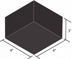
Depth: When using brick to turn an arch, this is typically the length of the rowlock or the solider (approximately 4 or 8 inches).
Extrados and Intrados: The upper and lower radius of the arch turned masonry units.
Keystone: This is the unit placed in the center of the crown and typically one of the last units placed when constructing the arch.
Rise of an arch: This is one of the most important dimensions when laying out an arch. This defines the height of the arch from the top of the jamb to the bottom of the arch (intrados).
Skewback: This is where the veneer becomes the arch. Typically begins at the inclined turned masonry units.
Soffit: Sometimes it is an interchangeable word with the intrados. It is another term for the bottom of the arch. Many tradesmen simply call the bottom of the arch the “bottom of the arch”.
Span: There are two definitions for the span. For simple arches, span (S) is simply the rough opening or the distance between the finished veneer of the jambs. This is the way this term will be used in the field. The less used and more complicated definition is when an arch is a larger circular arch and the span (L) is the distance between the ends of the arch axis at the skewback.
Spring line: This this where the soffit of the arch meets the jamb of the masonry below the arch.
Now we can get to the good part.
Laying out an arch is a bit more complicated than creating a radius between the jambs. The type of arch you have to layout will dictate the steps that need to be followed.
Segmental arches are typically just slightly curved above the top of the jambs and are not full half circles. Layout for these arches require you to understand what the rise, radius and span are for the arch.
Here is a formula to calculate the radius of the arch so you can build the template.
(span inches x ½) x (span inches x ½) = T square inches
T square inches /rise inches= S inches (this is distance from bottom of arch and the remainder of the diameter of the arc circle)
T + S= U inches (this is the diameter of the entire arc circle)
U/2 = R is the radius of the arc circle. This is the dimension that you will need to make your template.
Here is an example:
- Span = 60 inches
- Rise = 12 inches
- Radius = (this is what needs to be calculated)
- 60 inches (span) x ½ =30 inches (this is T).
- 30 inches x 30 inches = 900 square inches (T x ½ span = Square inches).
- 900 square inches / 12 inches (rise) = 75 inches (this is S, the diameter of the arc circle – the rise).
- 75 inches (which is the diameter minus the rise) + 12 inches (the rise of the arch) = (this is U, the diameter of the circle). 87 inches is the diameter of the arc circle.
- 87 inches / 2 = 43.5 inches (this is R, this is the radius of the circle). The radius of the circle will be used to construct the template of a Segmental arch, 60 inches in span with 12 inches of rise.
Laying out a semicircular arch is much easier than a segmental arch. Here you need to know the span of the arch and the rise. The radius of the arch is ½ the span and the radius are drawn from the base of the rise on the template.
When building the arch template many of us use plywood at least 5/8 inch, but preferably ¾ inch for the sides of the arch on very large arches. The two circular halves will be parallel and placed together using pieces of 2-inch by 4-inch material. It is always a good idea to use screws to put the arch template together as it can ease removal when scaffolding or other temporary items would interfere with removal of an entire template after the arch is constructed. The top of the template performs well when ¼ inch plywood is used to form a clean radius.
The ¼ inch plywood will absorb water but can be reused for repetitive window openings, making it worth the effort to use. ¼ inch plywood is my preference for the top of the template, but I have seen poster board, cardboard, and carpet turned upside down to form the bottom of the arch. If it works, stick with it. The biggest thing when setting the arch template is to use wedges at the spring line location. The wedges will allow you the ability to drop the template down and make the arch removal easier.
If it is too easy to remove, then the brick at the spring line may end up being a bit out of place and it will show up once everything is cleaned and pointed. Everyone is different when it comes to arch laying preference. I build a better arch when I tuckpoint the bottom of the arch once the form is removed. I feel I can construct the arch cleaner and I do not have to spend nearly as much time cleaning over my head with cleaners. You can butter the entire brick and lay them as a rowlock if you are comfortable with that approach.
When we edited the NCCER Level 3 Masonry Manual, Fourth Edition pages 4-13, we updated and simplified many of the diagrams and text in the arch section. We went into a lot of detail on Jack arches, Gothic arches and even Multicentered arches. If you have any questions, this would be a good point of reference.
Part 3: Benefits of specifying complete masonry veneer wall systems
 By Herbert Slone, RA, and Art Fox
This is part three of a seven-part series of blog entries about the benefits of specifying and building with manufacturer-tested and warrantied wall systems compared to specifying individual components. Benefits include a much faster design and specification process, proven component compatibility, faster component installation and better performance, plus the peace of mind that comes from knowing all components are proven compatible and will perform as specified. Part three provides a look at vapor barriers.
Vapor barriers
Vapor barriers control the rate at which moisture moves in and out so the wall can dry. Many variables go into choosing and placing the correct barrier. For example, should it be located on the warm or cold side of the cavity? Since vapor will always move into the wall from the high-vapor-pressure (moister)
side of the wall, and migrate to the low-pressure (drier) side, the rule of thumb is the barrier always goes on the high-pressure side. This generally means the barrier goes on the interior or ‘heated’ side in northern locations, and on the exterior ‘high humidity’ side in the south. In the middle states, vapor barrier placement and the question of whether one should be used are a bit ambiguous. In such situations, further hygrothermal evaluation should be done by a qualified expert—often consultants or insulation manufacturers—using tools considering climate, building materials, HVAC systems, and building function.
In addition to placement, it is equally critical to decide between high- or low-perm barriers. Part of the vapor management consideration also involves the absorptive capability of the other components in the wall itself. All building materials absorb water, reservoir it, and then release it as conditions change, so one must account for these conditions as well.
A good place to start researching vapor barriers is the International Building Code (IBC) Section 1405.3, “Vapor Retarders,” which has definitions of and perm ratings for vapor barriers. The higher a material’s perm rating, the more permeable it is to water vapor. A Class I vapor barrier is a material with a perm rating of less than 0.1, which is at the level of polyethylenes or trilaminates like foil scrim kraft materials. Class II barriers have a permeance of greater than 0.1, but less than or equal to one, which is typical of fiberglass facers like a foil or kraft paper facer. Finally, there are the Class III barriers, which include all barriers with a perm rating greater than one and less than or equal to 10, such as common wall paint.
When it comes to placing the vapor barrier, IBC says a wall with continuous insulation is more tolerant of moisture because it stays warmer; therefore, condensation inside the wall becomes less of a possibility. If the cladding is back-ventilated, as it is in a masonry cavity wall, the wall can dry faster and more completely, which influences the vapor barrier choice. Given there are so many interdependent variables, and because each building and region creates a dynamic and unique set of conditions, a hydrothermal analysis, such as can be provided by WUFI software, is often helpful.
WUFI allows realistic calculation of the transient coupled one- and two-dimensional heat and moisture transport in walls and other multilayer building components exposed to natural weather, enabling a full understanding of how all the layers of the wall perform together to manage vapor and air movement under thermal conditions that vary by hour over years.
In addition to understanding the way vapor barriers handle moisture, it is necessary to consider their flame spread ratings. Typically, steel stud/brick veneer construction is classified by IBC as Type I or II construction and its insulation must use a facer with a flame spread less than or equal to 25 when tested in accordance with ASTM.
Be sure to come back to part four of this blog to learn about through-wall flashing, mortar dropping collectors and weep vents.
Part 2: Benefits of specifying complete masonry veneer wall systems
 By Herbert Slone, RA, and Art Fox
This is part two of a seven-part series of blog entries about the benefits of specifying and building with manufacturer-tested and warrantied wall systems compared to specifying individual components. Benefits include a much faster design and specification process, proven component compatibility, faster component installation and better performance, plus the peace of mind that comes from knowing all components are proven compatible and will perform as specified. Part two includes an introduction to moisture management, including the definition and functions of water resistive barriers and air barriers. Part three will continue the discussion of water resistive barriers with a look at vapor barriers.
Moisture management
Moisture management means not only getting water out of the wall, but also allowing air into the wall so it can dry quickly and completely. Since water infiltration poses a significant danger to walls, it is wise to take a redundant approach to moisture management. Redundancy means there are multiple planes of defense against moisture intrusion.
These multiple planes include first the watershed at the face of the cladding or veneer. Behind that is an air space encouraging water to drain out of the wall, breaking the directly connecting path for water to enter the wall. The third redundancy is the use of a highly water-resistant, continuous insulation layer such as extruded polystyrene (XPS), which will shed rather than absorb any water that makes it to the board’s face. (Another insulation option would be polyisocyanurate [polyiso]. Expanded polystyrene [EPS], sprayed polyurethane foam [SPF], and mineral wool could also be used as continuous insulation, but they are not as water-resistant as XPS.) The final line of defense is the water-resistive barrier itself, often installed behind the continuous insulation and over the exterior-grade gypsum sheathing. All the redundant layers are a natural part of masonry veneer construction.
Water-resistive barrier
Air- and water-resistive barriers are often a single product, the same layer in the wall which resists bulk water penetration and wind-driven rain penetrating the exterior cladding. This contrasts with vapor, which either enters the wall system by permeation or is carried into it by air leakage. In a complete wall system, depending on the regional design considerations, the functions of the air barrier, vapor barrier, and WRB are sometimes combined in one product—frequently, a liquid product that is roller- or spray-applied. Greater efficiencies can be achieved if only one trade is involved in applying the all-in-one type of product instead of multiple trades applying each of the air-, vapor-, and water-resistive barriers.
Air barriers
Air barriers have a strong influence on energy efficiency. It is estimated air leakage is responsible for about six percent of total energy used by commercial buildings in the U.S. About 15 percent of primary energy consumption in commercial buildings attributable to fenestration and building envelope components in 2010 was due to air leakage. (For more, visit www.airbarrier.org/wp-content/uploads/2017/06/Buildings-XIII_OnlineAirtightnessCalculator_V5.pdf[3].) Air barriers are often also weather-protective and water-resistant. They allow the building envelope to prevent accumulation of water in the building and establish a drainage plane inside the wall.
Be sure to come back to part three of this blog to learn about vapor barriers.
Part 1: Benefits of specifying complete masonry veneer wall systems
By Herbert Slone, RA, and Art Fox
This is part one of a seven-part series of blog entries about the benefits of specifying and building with manufacturer-tested and warrantied wall systems compared to specifying individual components. Benefits include a much faster design and specification process, proven component compatibility, faster component installation and better performance, plus the peace of mind that comes from knowing all components are proven compatible and will perform as specified. Part one describes the components of a masonry veneer wall system and the tests a wall system must pass to provide optimal performance.
A masonry cavity wall system must successfully perform multiple functions throughout the life of the building. A proper wall is expected to manage moisture, air, and heat, contain fire, and hold up the structure itself. For a wall to perform all these functions, specifications should include all the products necessary for the components to work together.
For the contractor, building a masonry cavity wall is just as challenging as specifying it is for the architect. Contractors rely on the architect for highly precise drawings and specifications so they can produce an accurate bid. They want to be able to build with familiar, proven methods and materials that are compatible and readily available through distribution.
For these reasons, specifying a complete wall system with all the components tested and warrantied together can offer many advantages to the design professional, such as helping support risk management. The design professional’s ability to thrive depends on his or her ability to provide timely documentation for the building’s performance.
Components of a masonry veneer wall system
The structural components forming the basis of the substrate may be steel or wood studs or concrete masonry units (CMUs). On the outside is the weather-resistant component—the cladding or masonry veneer. Between those are three functional component categories that complete the wall system and make the wall perform: moisture/air, thermal, and structural management.
Moisture/air management relies on:
- an air- or water-resistive barrier (WRB);
- a vapor barrier;
- through-wall flashing (including mortar dropping collection and weep vents); and
- water- and air-sealing washers on fasteners.
Thermal management involves:
- insulation between the stud framing;
- continuous insulation (CI) outside and over the framing; and
- fire safing insulation.
Structural management depends on:
- masonry anchors;
- wall ties; and
- water- and air-sealing washers on fasteners.
Systemization
Having all the right components in the wall is not enough. A true wall system must have passed extensive testing proving the components, as a system, meet the code-mandated performance criteria and are physically and chemically compatible. Further, the system must pass industry-standard tests, such as:
- National Fire Protection Association (NFPA) 285, Standard Fire Test Method for Evaluation of Fire Propagation Characteristics of Exterior Nonloadbearing Wall Assemblies Containing Combustible Components;
- ASTM E119, Standard Test Methods for Fire Tests of Building Construction and Materials;
- ASTM E2307, Standard Test Method for Determining Fire Resistance of Perimeter Fire Barriers Using Intermediate-scale, Multistory Test Apparatus
(used only for joint firestopping); - ASTM E331, Standard Test Method for Water Penetration of Exterior Windows, Skylights, Doors, and Curtain Walls by Uniform Static Air Pressure Difference; and
- ASTM E2357, Standard Test Method for Determining Air Leakage of Air Barrier Assemblies.
Individual product components of the system can also provide the protection of a warranty that covers them against defects. In the event there is a problem, unified and cooperative solutions are best rather than multiple companies acting separately.
Be sure to come back to this blog for part two to learn about moisture management, including a discussion of water-resistive barriers and air barriers.